Pressure considerations for reservoir inlet control valves
/Both pressure and flow velocity must be considered when designing reservoir level control systems.
For reservoir level control valves, anything above 4 to 5 bar is high pressure. Pressures above 6 to 8 bar can be disastrous for control valves if precautions are not taken. This is because cavitation can lead to rapid erosion of the valve body. We’ve seen holes in valve bodies after only a few weeks of extreme cavitation.
Cavitation is the phenomena of bubbles forming at low pressures and then collapsing when the pressure builds up. The collapsing causes a high velocity jet inside the bubble. The jet is powerful enough to erode the valve body or other metallic parts.

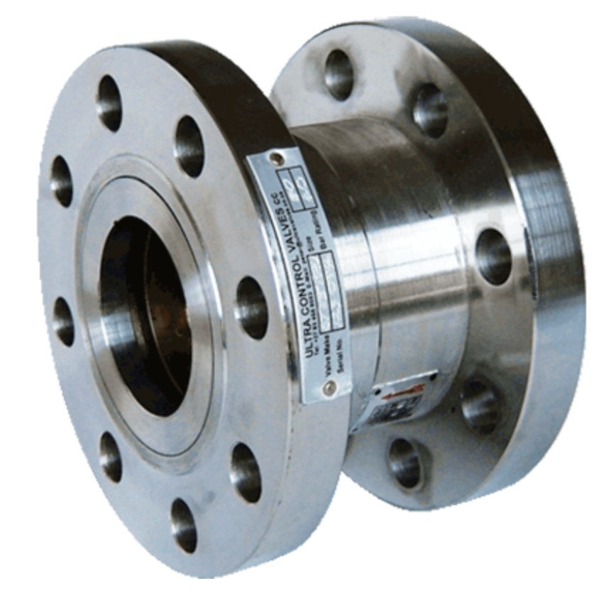
The safe operating range - where cavitation is unlikely - is usually expressed as a ratio between upstream and downstream pressure. A typical self-actuated globe control valve used in the water industry might have a 3:1 ratio. That means if the upstream pressure was 12 bar the downstream pressure could be as low as 4 bar before cavitation set in. Some diaphragm-actuated globe control valves allow for a higher ratio because of the flow pattern in the valve body. For instance, the Ultra Alpine Control Valve can handle a 4:1 pressure difference.
To prevent cavitation the ratio between upstream and downstream pressure should not exceed the designed range.
Velocity considerations for reservoir inlet control valves
Every control valve has a maximum allowable flow velocity to ensure good controllability, long life and low noise levels. For standard diaphragm-actuated globe pattern valves it is about 6m/s for 24/7 operation. Exceeding this by up to 20% for a few hours a day is acceptable.
Axial flow type control valves are able to accept higher velocities due to the flow pattern through the valve. The velocity is often expressed in terms of flow rate.
Consider a typical 200mm diaphragm-actuated globe control valve in a reservoir. The inlet pressure is 4 bar inlet and the back pressure from the reservoir head is 1 bar.
A typical valve might have an acceptable pressure drop ratio of 4:1 (to prevent cavitation) and an acceptable flow rate of 200 l/s.
The sizing formulae for control valves is Q = Cv √ dP where:-
Q = flow rate.
Cv = the fully open capacity for the valve.
dP = the differential pressure across the valve.
Using the formula above you’ll see that if the valve was fully opened the flow rate would be 329 l/s. Operating this valve under these conditions would result in a much reduced life span. If you did the calculation for other valves you’d see that the maximum recommended flow rate is reached with a differential pressure of around 1.5 bar.
So how do we ensure that the valve operates within the pressure drop and flow rate design parameters?
Limit the flow
In cases where the dynamic head is greater than 3 bar, and the static head is 10m or less, a rate of flow control feature is recommended for the level control valve.
An alternative is to add something like the Maric Flow Control Valve to the system. It’s simple, tamper proof and adds another back pressure device.
Limit the pressure drop ratio
This is a little more complex and requires some judgement. Let me explain.
An artificial back pressure device like an orifice plate can provide the designed back pressure only at the design flow rate. When the flow rate changes the back pressure changes.
Consider an installation with a valve designed for a 3:1 pressure drop. The dynamic upstream pressure is 9 bar and the head from the reservoir is 1 bar. We’d need an additional 2 bar of back pressure to get to the acceptable 3:1 ratio. This could be accomplished using an orifice plate.
But, here’s the problem. An orifice plate is sized to produce a specific pressure drop at a specific flow rate. Reservoir valves must normally open and close slowly to avoid water hammer. In some instances it can take 10 minutes or more to go from closed to open or the other way.
During this time the flow rate through the valve body is not at the rate for which the orifice plate was designed. The orifice plate doesn’t produce the expected back pressure and there is potential for cavitation to occur. One has to exercise judgement to decide if the duration and size of the pressure drop is likely to lead to cavitation and damage to the valve.
If it is, a pressure reducing valve may have to be installed upstream of the level control valve. The pressure reducing valve will ensure that the level control valve operates within its design parameters during normal operation and during opening or closing.
A ratio reducing valve is a good candidate for this as it is simple, stable and requires no maintenance.
Conclusion
Although water control valves are designed to destroy energy and, in some cases, handle pressures of up to 250 bar they can be vulnerable to cavitation and velocity damage at low pressures. It is the Engineer’s duty to ensure that the level control valves operate within their design parameters.
Peter Telle BSc (Mech) Eng MBL Ultra Control Valves cc www.ultravalves.co.za

