Upthrusting in Boreholes
/There is a common perception in the pump industry that a selection is done based on a duty “point”. If only life was that simple and change wasn’t an integral part of our daily lives. If fluid systems were approached from a duty “range” perspective, would this be an exercise in semantics or reality? Admittedly some systems do have very small changes in the flow rates and Total Dynamic Heads (TDH) but elements in a system are constantly changing. Tanks/sumps fill and empty, the levels of rivers, dams and boreholes fluctuate and pressures in vessels change with process requirements. The net result of these changes is that operating conditions are created that force a pump to operate far to the left or right of the best efficiency point with serious implications for energy efficiency, Mean Time Between Failures (MTBF) and plant reliability.
Figure 1: System curve for 32mm HDPE pipe and + pump curve for borehole static and dynamic water levels
Possibly one of the best (or worst!) examples of applications that have large variations in TDH are groundwater or borehole installations. Not only do water levels in the hole vary from season to season but porosity and transmissivity within the aquifer almost always cause significant changes in water levels. Recently we had the opportunity to share in the process of optimising a system that had a static water level of 20m while the level fell a further 65m when the pump was switched on. Figure 1 graphically represents the problem.
Curve A shows the system curve for a 32mm class 12 HDPE rising main at a static level of 20m. Curve B is the system curve for the same rising main at the new (dynamic) level of 85m (20m + 65m drawdown). The blue curve shows the pump performance while the dotted red extensions show duty points that are not recommended by the manufacturer. At a static head of 20m (start up) the pump will operate at 31l/m against a head of 22m. This is well outside the manufacturer’s recommended range. As the water level falls to the dynamic level (inflow now equals outflow), the duty point becomes more acceptable at 8l/m against a head of 88m. Assume for a moment that the static water level in the hole increased to, say 10m (higher rainfall, improved recharge) then curve A will move down to 10m and the time the pump will spend on the extreme right hand side of the curve will also increase. The usual failure symptoms for operation on the right hand side of curve are motor thrust bearing and/or coupling and/or winding failure. The pump end will also have a sharply reduced operating life due to failure of the (up) thrust mechanisms built into the pump end.

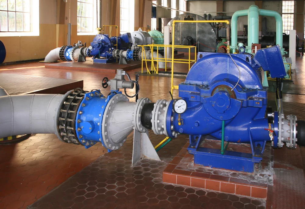
Figure 2: 150kW mine dewatering pump
While this case study covers a relatively small pump set, it still represents a substantial investment for the end-user. In addition, the application could just as well be a multi megawatt shaft dewatering pump. A recent example of this required the water in an abandoned shaft, in the DRC, to be lowered from 120m to 280m. Failure in a system such as this is definitely not an option!
Stopping the pump for a matter of hours, allows not only the recovery of the water level but very costly delays in the reopening of the mine. Removal, repair and reinstallation of the pump set and rising main is a hazardous, time consuming and expensive exercise.
How can these extreme duty ranges be handled? Here’s a look at some design options that will prevent pumps and motors from tearing themselves apart.
In the application shown in Figure 1, we had a borehole that had maximum and minimum TDHs that effectively pushed the pump to points that were too far left and right of the Best Efficiency Point (BEP). Some of the usual solutions to this problem are:
Installing a throttling valve at the discharge. Some of the drawbacks? Unauthorised tampering, use of cheap non-control pattern valves (yes this IS a control valve application). If globe valves, characterised butterfly valves and ball type valves are used, they become expensive and require another level of skill to set and maintain. They are also prone to the “fiddle factor”.
If the static head is the main culprit (as was the case with our borehole) a smaller rising main can be installed to prevent the pump “falling off” the r.h.s. of the curve. The disadvantage here is that the losses incurred in the pipe remain for both the start up flow and for the minimum flow.
Admittedly the losses do decrease as the flow decreases but what is needed here is something with a bit of intelligence!
Figure 3: New system head curves with self adjusting control valves
In searching for an elegant solution to this vexing problem, I came across a valve that seems to have some good potential for making a positive contribution to improving overall system efficiency and reliability. The Figure 3 graphically shows the same installation fitted with a proprietary control valve, freely available in Southern Africa.
Curves A & B are the system curves for the 32mm class 12 HDPE rising main. Curves C & D are the combined curves for a particular control valve and the piping system. The valve has a set point of 26l/m. Notice how the curves become very steep as flows approach the rated figure. This flow rate is exactly where the work of supporting the pump needs to be done. At lower flows the gradient is flat which is good as this represents lower losses. As the flow decreases as a result of increasing static heads, so the losses need to be decreased. From the diagram, the head loss at maximum flow is about 22m (the gap between curve A and the intersection of curve C and the blue pump curve). As the water level in the borehole falls, so the combined system curve rises up. At the minimum flow (8l/m) the gap between pipe curve B and the intersection of the combined system curve (D) and the pump curve is now only +/-3m. This is potentially an intelligent solution with few, if any, of the traditional drawbacks associated with borehole pump control.
John Tonkin is the editor of the Journal and offers training and advisory services at John Tonkin and Associates. His areas of specialism include pumps, pipes and valves within the system as a whole. For more information on the advantages and disadvantages of the various measures available to prevent damage due to upthrusting in borehole pumps, John can be contacted at editor@bwa.co.za.

