
Why did my pump stop delivering water?
/John Tonkin
All too often when a pump stops delivering water it is removed, repaired and reinstalled in the same conditions. A costly exercise which invariably leads to the same fault occurring. Perhaps it is worth looking at how a well-known car manufacturer handles a fault condition.
Situation: The car stopped at the side of the road.
Question: Why did the car stop? Answer: Because the engine seized.
Question: Why did the engine seize? Answer: Because the oil sump drained.
Question: Why did the oil drain? Answer: Because the plug fell out.
Question: Why did the plug fall out? Answer: Because the incorrect tightening procedure was used.
A similar approach can be adopted in the pump industry. A detailed and careful look at the performance history of the installation and the symptoms of failure will lead to corrective or remedial actions being taken to prevent a similar failure from occurring in the future.
This process is known as a Root Cause Analysis, or RCA. In this article, we will discuss the various tools that are available to carry out a Root Cause Analysis and then look at some reasons why pumps fail.
Tools for gathering information
Electrical data
With advances in technology, the gathering of accurate and relevant data has improved significantly. Protection relays that are capable of doing a basic data logging function right through to SCADA systems that collect large quantities of historical data, which can be subjected to trend and other types of analysis, all contribute to making the task of root cause analysis so much easier.
Here is an example of a data set extracted from an electrical pumping system management relay.

Pressure gauges for measuring negative or positive pressure
The installation of good quality pressure gauges on both the suction and discharge sides of a pump will give good feedback with regard to the position on the curve at which the pump is operating. A gauge on the suction side will give a clear indication of the amount of negative or positive pressure in the suction line and this can be related back to the pump’s NPSH required.
Flow meters for measuring the rate of flow
There are two broad categories of flow meters, namely, intrusive and non-intrusive. Intrusive flow meters are immersed in the liquid being measured. Most prominent in the non-intrusive range of flow meters are the ultrasonic units, which make use of an electromagnetic pulse to measure the rate of flow through a pipe of known dimensions.
A coal mine in the Witbank area used a basic totalising flow meter together with an hour meter to monitor the efficiency and condition of their dewatering pumps. The hours run and the equivalent amount of water pumped in these hours were recorded each week. Once a pump reached a predetermined level of capacity decline, it was replaced with a standby unit and sent for rework or repair.
Clamp meters for measuring current
In installations that are powered by electric motors, the clamp meter (sometimes called a “tong tester") has become indispensable to not only the service technician but also the designer who seeks to gather more information on the conditions, which exist at site. Instruments, which are available at reasonable prices, are capable of measuring amps, volts, resistance, capacitance and temperature to a very acceptable level of accuracy. All too often, failure of the motor is seen as the preserve of the electrical department. In many of these cases, the root cause of the failure could have been mechanical and sometimes hydraulic. Merely repairing the motor by rewinding it and replacing bearings will not necessarily prevent another failure from occurring.
Tachometers for measuring the shaft speed
The actual shaft speed is an important input into the process of analysing the performance of a pump. One manufacturer could not understand why a pump fitted to a single-phase motor was overloading the motor while the exact same unit was running within specification on a three-phase motor. Once a tachometer was used to measure the shaft speed of the respective motors, it was found that the rpm of the single-phase unit was higher than the three-phase unit. The affinity laws state that power varies to the cube of the shaft speed. It therefore does not take much of an increase in the speed of the pump before there is a noticeable difference in the power consumed.
Power meter for measuring motor input power
Using the readings obtained from the flow meter, pressure gauges (suction and discharge) and the power meter, the pump efficiency can be ascertained. A real-time pump performance curve, including efficiency, can also be drawn.
Temperature measuring devices both contact and non-contact types
Infrared temperature measurement devices are a quick and effective method for measuring the temperature of operating machines. These instruments are used extensively in the checking of large electrical panels to identify hot connections and other sources of heat build-up. Small handheld thermometers which use a laser beam to measure temperature are quite affordable. The level of accuracy that a regularly calibrated unit offers is quite adequate for use in the monitoring of pump installations.
Vibration recorders
Once again, advances in the electronics and software industries have opened up some significant opportunities for system monitoring and maintenance using vibration as the measured parameter. Simple units are available which will only measure the displacement or amplitude of the vibration in three planes. All the recognised pump construction and testing specifications worldwide have maximum allowable values for vibration. Recent developments in the software industry have seen the release of a number of programs that will do a full spectrum analysis of the raw data collected from the installation. The opportunity now exists to drill down into the data and isolate the source of any vibration with a high degree of accuracy. This data is also used to assess the potential for failure in bearings and other components. Remedial steps can therefore be planned and implemented in the most cost-effective manner.
Examples of trouble-shooting
Case 1: Cavitation due to poor suction conditions

Pump failure due to cavitation caused by NPSHr > NPSHa
Close examination of the impeller vanes shows some significant cavitation damage to the front of the vanes. This indicates that the bubbles were formed in the suction area of the pump possibly because the suction pressure required by the pump (NPSHr) was substantially higher than the suction pressure available at site. Kind of like a big spenders small bank balance!
A suction pressure gauge will give immediate feedback of lower than normal values. Pressure transducers can convert these readings into digital values and a Internet of Things (IoT) unit can transmit real time information to anywhere in the world.
Close inspection of the hub shows the outline of the impeller retaining nut. From this it appears that the nut has worked its way loose, which has allowed the impeller to wobble on the shaft. Another indicator of a loose nut is the wear pattern on the front of the neck ring. The noise emanating from this pump must have been quite extraordinary.

Reverse side of the same impeller. Vanes are Not damaged
The cavitation most likely came from an excessive suction lift, suction pipes that are too small, a partially blocked inlet or a higher than normal liquid temperature. The vibration resulting from the cavitation caused the impeller nut to work its way loose.
If all the costs were added up, this was a very costly failure. Besides the cost of repairs, there is the cost of production losses, downtime and transport.
Case 2: Cavitation due to suction and discharge recirculation

This impeller has been subjected to cavitation caused by recirculation in the impeller discharge.
The reasons for this damage could be one of many, for example, operating under low flow conditions (too far to the left on the operating curve); blocked discharge filters; discharge valves that are 90% closed; or pumps in parallel that are mismatched.
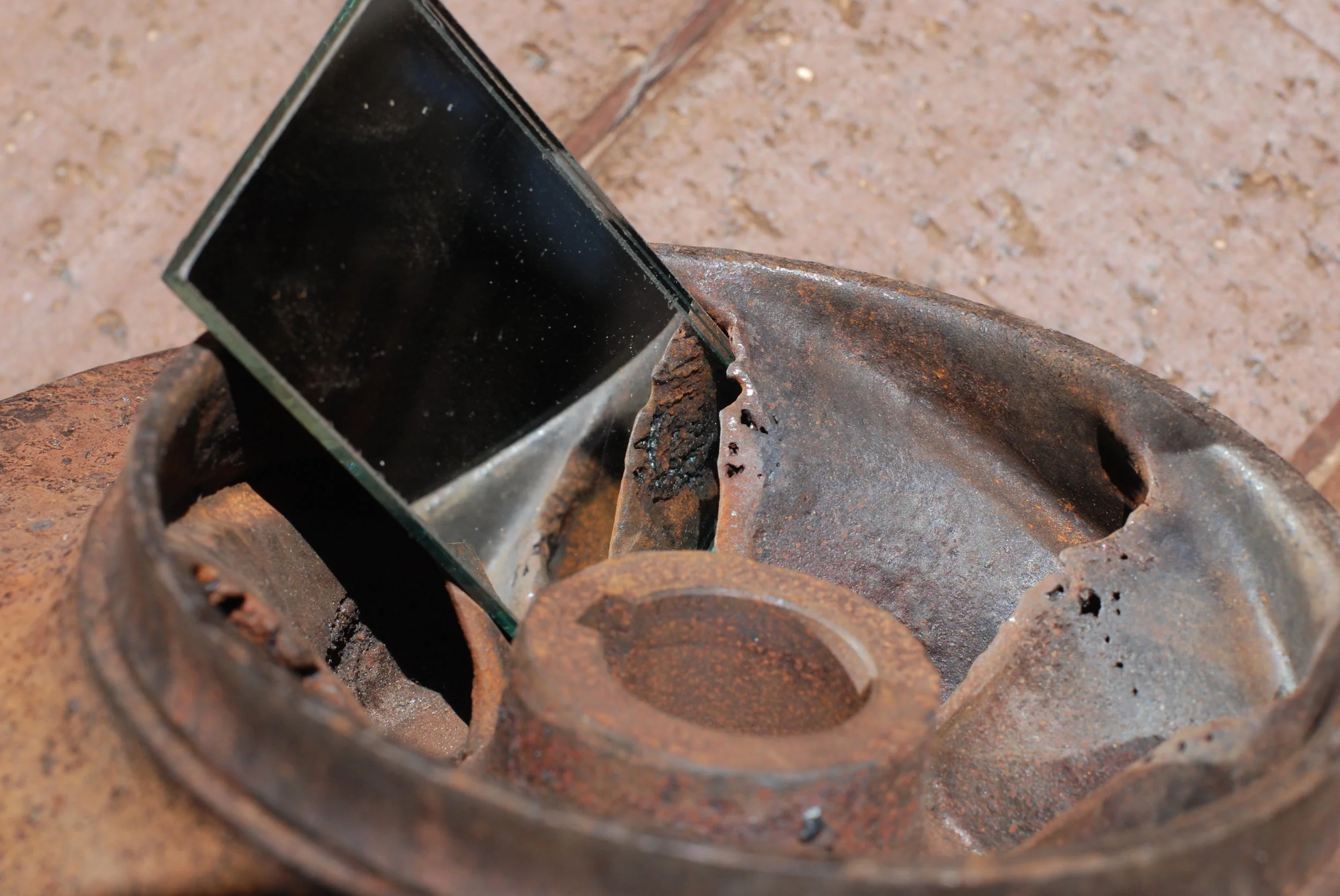
Here is a good example of damage to the reverse (pressure side of an impeller) starting at the vane tips. Having a mirror close at hand when examining a failed pump could be extremely useful!
It should be noted that this impeller is also damaged on the low pressure (front) side of the vane. There is a high probability that this pump is being forced to operate over a wide range both left and right of the Best Efficiency Point (BEP).
In both these cases, pressure gauges, electrical relays and vibration recording instruments would give clear indications of sub-standard performance and impending problems.
Conclusion
If your pump stops delivering water, take time to find out why by making use of all the tools available to do an in-depth Root Cause Analysis (RCA). A sustainable and cost-effective system will be the reward!

